App installieren
So wird die App in iOS installiert
Folge dem Video um zu sehen, wie unsere Website als Web-App auf dem Startbildschirm installiert werden kann.
Anmerkung: This feature may not be available in some browsers.
Du verwendest einen veralteten Browser. Es ist möglich, dass diese oder andere Websites nicht korrekt angezeigt werden.
Du solltest ein Upgrade durchführen oder einen alternativen Browser verwenden.
Du solltest ein Upgrade durchführen oder einen alternativen Browser verwenden.
E
EnsureSound
.

S
savagedog
..
StormB schrieb:Danke
bin mit dem Ergebnis auch sehr sehr zufrieden
muß nur noch ein paar kleinigkeiten machen,
stärkere Seitenteile zur Zeit sind die aus Sperrholz sind mir zu dünn
Rückseite müssen noch ein paar Buchsen eingebaut werden
das wars aber auch schon....
Hi StormB, Sehr geil gemacht! Hast du zufällig eine Schematic für das Keyboard?
MFG DoG
hidiho savedog,
eine Schematic hab ich leider nicht aber
auf seite 2 von der Moog Prodigy wiring guide PCB.pdf von EnsureSound
ist ein Bild wie man eine Tastatur anschließt und welche Wiederstände man braucht
ist zwar keine Schematic aber Erklärt wie man es macht... ganz easy
hoffe du hast die Pdf Datei
Greetz
StormB
S
savagedog
..
StormB schrieb:hidiho savedog,
eine Schematic hab ich leider nicht aber
auf seite 2 von der Moog Prodigy wiring guide PCB.pdf von EnsureSound
ist ein Bild wie man eine Tastatur anschließt und welche Wiederstände man braucht
ist zwar keine Schematic aber Erklärt wie man es macht... ganz easy
hoffe du hast die Pdf Datei
Greetz
StormB
Danke habs gesehen
E
EnsureSound
.
Moog Prodigy clone DIY and MIDI CV
Hi All!!!
The promised video demo of my Moog Prodigy DIY clone:
Regards,
Ensure Sound
Hi All!!!
The promised video demo of my Moog Prodigy DIY clone:
Regards,
Ensure Sound
Check Mate
Aquatic Beta Particle
Hi Dmitry...
Great work!! Where did you have the case made if I may ask?
And another technical question...where do you get the Power for the MIDI to CV Interface from. You told me once that I'd need an extra transformer for that and therefore 2 power supplies. I only spot one power cable.
Cheers
Great work!! Where did you have the case made if I may ask?
And another technical question...where do you get the Power for the MIDI to CV Interface from. You told me once that I'd need an extra transformer for that and therefore 2 power supplies. I only spot one power cable.
Cheers
A
Anonymous
Guest
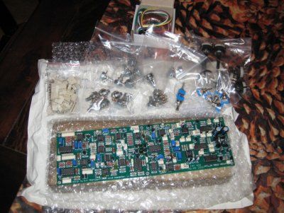
Klasse Projekt, habe ich das richtig gelesen, dass so eine bestückte Platine nur um die 250 EUR kostet?
E
EnsureSound
.
Check Mate schrieb:Hi Dmitry...
Great work!! Where did you have the case made if I may ask?
And another technical question...where do you get the Power for the MIDI to CV Interface from. You told me once that I'd need an extra transformer for that and therefore 2 power supplies. I only spot one power cable.
Cheers
Hi!
Power to the MIDI controller you can take with the main board +12V and -12V.
I left the only stabilizer + 5V supply for MCU and DAC.
If you look at the circuit, I think it's all clear.
Regards,
Ensure Sound
Check Mate
Aquatic Beta Particle
Thanks...I'll look into it!! 
aven
||||||||||
sell the same as DIY kit on, with case, all components! great work!
S
savagedog
..
Hab 2,5m Logs gefunden (zwar Stereo aber who cares)
https://www.banzaimusic.com/Piher-6mm-s ... M-log.html
falls ihr woanders günstigere findet dann bitte bescheid geben!
https://www.banzaimusic.com/Piher-6mm-s ... M-log.html
falls ihr woanders günstigere findet dann bitte bescheid geben!
F
FNT
.
@StormB: Are there more pictures from your great looking case behind the f***ing google login page? I'm really interested how to build such a case. I know, it looks easy but for a lot of people (at least for me) it isn't. ")
@LED-man/EnsureSound: Also interested how to get the film(?) for this Hammond or Bopla case.
@LED-man/EnsureSound: Also interested how to get the film(?) for this Hammond or Bopla case.
LED-man
.
FNT schrieb:@StormB: Are there more pictures from your great looking case behind the f***ing google login page? I'm really interested how to build such a case. I know, it looks easy but for a lot of people (at least for me) it isn't.
@LED-man/EnsureSound: Also interested how to get the film(?) for this Hammond or Bopla case.
Ask a copy shop for a stickerprint (adhessiv paper), tape it on the panel/case, use clear varnish for scratch resistance.
feel free to design your own panel with Adobe illustrator or use frontpanel designer and export it to pdf (check the export size for 1:1 measurement)
i paid 2,50€ for a DIN A3 paper like this:

F
FNT
.
I'm not a big fan of paper. Thought more of a self adhesive (plastic) film. Like the ones sold with the Yocto initially (the 3M stuff).
citric acid
||||||||||
F
fredp
long time no see - Klicke Reset Passwort
Hi guys, would someone have some bare Prodigy and midi PCB to sell as it looks like Dmitry has no more of them in offer... if yes just send me a PM...
Thanks
Thanks
S
savagedog
..
Wird bei euch der PIC16C84 (CV Gate) auch so heiß oder ist irgendwo der wurm hier schon drin?
S
savagedog
..
Could it be that the U6 - U7 of the Midi cv converter are wrong on the PCB? Like the Schematic it schould be 5V in the middle or iam wrong now?
Level5
Alter (Dudel) Sack
Ich habe es gerade mal überprüft: die beiden Spannungsregler U6 und U7 sind tatsächlich vertauscht, auch im Schaltplan 
Da mir noch ein paar Teile für die Platine fehlen, hatte ich bisher noch keine Testmöglichkeit, werde die Regler aber gleich mal tauschen.
Dein PIC dürfte dadurch das Zeitliche gesegnet haben
Da mir noch ein paar Teile für die Platine fehlen, hatte ich bisher noch keine Testmöglichkeit, werde die Regler aber gleich mal tauschen.
Dein PIC dürfte dadurch das Zeitliche gesegnet haben
S
savagedog
..
Level5 schrieb:Ich habe es gerade mal überprüft: die beiden Spannungsregler U6 und U7 sind tatsächlich vertauscht, auch im Schaltplan
Da mir noch ein paar Teile für die Platine fehlen, hatte ich bisher noch keine Testmöglichkeit, werde die Regler aber gleich mal tauschen.
Dein PIC dürfte dadurch das Zeitliche gesegnet haben
das hoffe ich doch mal nicht :/ ansonsten wäre es schon derbe fail
S
savagedog
..
Anyone know a good workflow for the Tuning and trimming of the Prodigy?
S
savagedog
..
And what Adjustments and Assignements we have to do? fe for the Temp ect. and frequence of cutoff?
3
3456778674
Guest
Have a look at the prodigy service manual, it has the procedures and the sequence in which they have to be done.
In total all of the provides trimmers have to be moved to the proper position - that is what they are for.
In total all of the provides trimmers have to be moved to the proper position - that is what they are for.
S
savagedog
..
nordcore schrieb:In total all of the provides trimmers have to be moved to the proper position - that is what they are for.
hehe really?
joke apart, have you a link to the manual? I just saw a youtube vid and the whole based on other Positions in shematic what i have seen (for example the R17 has to be 0.689 volt) but R17 is different from R17 of the clone.
Bodo
Gnabbldiwörz!
savagedog schrieb:have you a link to the manual?
http://www.cyborgstudio.com/synthmp3s/m ... manual.pdf
It really must be very, very, very difficult to type "moog prodigy service manual" into Google and click one of the search results
Similar threads
News
-
 News Battles, Challenges und Musik die wir hier in Sequencer.de zusammen bauen findest du in…
- Gestartet von Moogulator
- Antworten: 0
-
Arbeitspferd-Synthesizer - Wie finde ich meinen Hauptsynthesizer?
- Gestartet von Moogulator
- Antworten: 1
-
News Heute - SequencerTalk 246 - Die Latenz ist weg & Gezielt Synthesizer finden.
- Gestartet von Moogulator
- Antworten: 1
-
-
News 5.Juli 2025, Berlin - Moogulator live im Synthesizer Museum, Berlin am Kotti (ehemalig Schneidersbüro)
- Gestartet von Moogulator
- Antworten: 1
-
-
News Happy Knobbing 2025 Bilder & Video - Modular Synth Meet - Dokumentation (Pfingsten)
- Gestartet von Moogulator
- Antworten: 19