Synthifreak
||||
Hallo !
Ich habe heute nach fast 20 Jahren meinen S1000HD mal wieder vorgekramt,weil ich eine 8MB Speichererweiterung bekommen habe. Ich habe nun 2x 8MB Speichererweiterungen drin und 2x2MB,also insgesamt 20MB.
Beim einschalten zeigt er mir nur 4Mwords an also 8MB. Wieso ??? Die eingebauten EPROMs sind 2.20.
Danke euch.
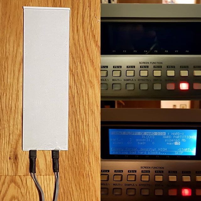
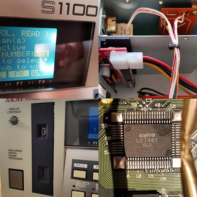
Das Display geht ist aber dunkel da muß ich mal die Folie erneuern. Es soll ja auch neue OLED Displays geben.Hat jemand Erfahrung damit ?
Danke.
Ich habe heute nach fast 20 Jahren meinen S1000HD mal wieder vorgekramt,weil ich eine 8MB Speichererweiterung bekommen habe. Ich habe nun 2x 8MB Speichererweiterungen drin und 2x2MB,also insgesamt 20MB.
Beim einschalten zeigt er mir nur 4Mwords an also 8MB. Wieso ??? Die eingebauten EPROMs sind 2.20.
Danke euch.
Das Display geht ist aber dunkel da muß ich mal die Folie erneuern. Es soll ja auch neue OLED Displays geben.Hat jemand Erfahrung damit ?
Danke.