Hi VeNoM ,
first and befor you set power on the Jeannie Motherboard control all Parts a second time .
Checklist:
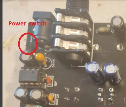
1- are the pins for the power swich shorten ?? (k5) Yes, I've used the jumper on those two pins.
2-is the tantal C 9 in the right direction ?? I think so, if I remember correctly, I've put the shorter leg into the negative hole. Is there a way to check if I made a mistake?
3- Is the IC6= LT 1054 in the right direction ?? Yes, the point on it is pointed to the condensator next to it.
4-78L08 and 79L08 on the right place - check it double . We had it now the second time that the regulators are in the wrong place . Yes.
5- check all solder points with a glass . I don't find any bad connections.
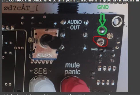
6: put the black cable from your measuring instrument on the ground
Ground is green (picture GND). you can solder a little cable on this point .
Dont forget to short the power switch , you can do it with a jumper . ( take the Jumper from the three pin Midi header ) I did that.
Have you a power supply 12 V - 1 A , center positive . Can be also 12 V 0,5 ... 1,5 A. Power supply is 12V 1500A with center +
OK , power up the jeannie with 12 V . Black cable to Ground , red cabel of your measuring instrument to the first FX 10 pin K1 connector .
You see there 3,3 3,3 ,,, GND,GND,GND,+8,+8, GND,-8,-8 direct on the PCB . This are the voltages . Example -8V can also be -7,88 V , or + 8 V can be 8,2 V...
First measure : is the 12 V there ?? This you can measure with black cable on the ground and red on the red pin of the 12 V plug. I get 12,25V from the adapter/12V plug. Is that too much? The adapter is brand new and it is from RockPower (Warwick).
If you have 12 V now you can measure 3,3 and +8 and - 8 V . All against ground . Means black cable on ground , red cable to 3,3 V , + 8 V and -8 Volt .
Hope this helps . Some of the voltages don't add up, please se the picture bellow.
G
Andre'